Modern vehicles are not just machines with engines—they are complex digital ecosystems filled with sensors, controllers, and actuators working together in real time. At the core of this coordination is a communication protocol known as CAN (Controller Area Network). In this article, we’ll explore what CAN is, why it matters in automotive systems, and how we implemented it in a real-world inspired HVAC (Heating, Ventilation, and Air Conditioning) control simulation using MATLAB Simulink.

Abhishek Malhotra
May 3, 2025
What is CAN?
CAN is a robust, multi master communication protocol developed by Bosch in the 1980s for in-vehicle communication. It allows multiple microcontrollers (called ECUs Electronic Control Units) to exchange information without needing a central host computer.
Each device on the CAN bus can:
Send data when it has something to share,
Listen continuously for incoming messages,
Filter messages based on message IDs (priorities).
Key characteristics of CAN:
Real-time performance
High fault tolerance
Supports multiple devices on a single bus
Message-based (not address-based), making it highly modular
Why Use CAN in Our HVAC Project?
Our HVAC project simulates a closed-loop thermal management system typical of modern vehicles. In an actual embedded automotive environment, data like fan speed, HVAC mode, and cabin temperature must be:
Transmitted between control units (e.g., from the HVAC controller to the dashboard or climate sensors),
Logged for diagnostics, and
Acted upon by other subsystems (e.g., the fan motor controller or compressor logic).
Instead of performing all logic in a centralized model, we used CAN to reflect how real automotive systems share sensor and control data across distributed nodes.

How We Implemented CAN
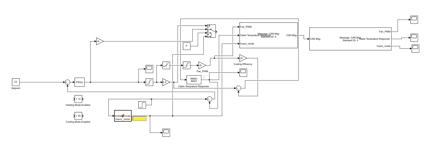
Modeled the HVAC system in Simulink and added CAN communication using these steps:
CAN Pack Block
The following outputs from the HVAC logic were packed into a CAN message:Fan_PWM(fan speed as a PWM value)HVAC_Mode(heating, cooling, or idle)Cabin_Temperature(sensed or calculated)
These were merged using a CAN Pack block with a message ID (e.g., 0x00), and transmitted with little-endian byte ordering.
Simulated Bus Transmission
The CAN message was virtually transmitted within Simulink, mimicking a real CAN bus environment.CAN Unpack Block
On the receiver side, the message was decoded using a CAN Unpack block, restoring individual signal values exactly as they would be received by a separate ECU.Display & Verification
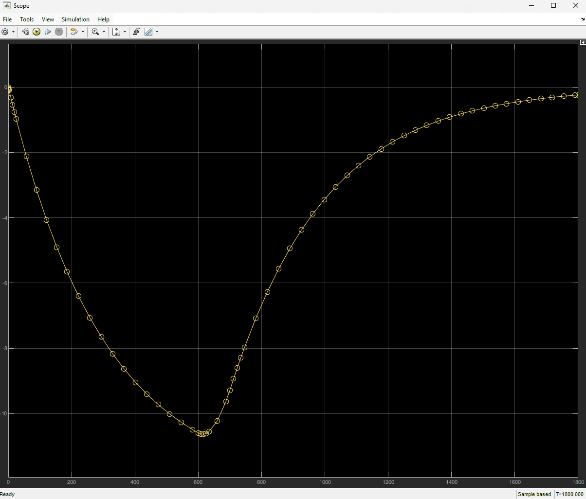
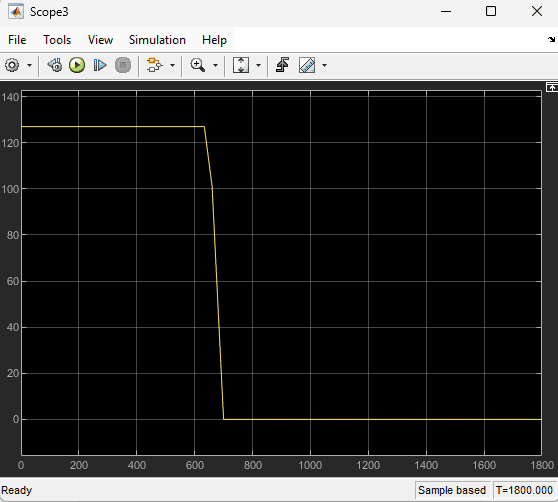
Scope and display blocks validated the values post-unpacking, confirming the signal flow and data integrity across the CAN system.
What This Demonstrates
Using CAN in the HVAC project showcases:
Practical automotive system design with realistic inter-ECU communication.
Simulation-to-hardware readiness for deploying control logic to embedded systems.
A strong grasp of distributed architecture, essential for modern embedded software engineers.
Conclusion
This HVAC CAN simulation project illustrates a scalable and realistic approach to modeling how thermal management and communication systems interact in a vehicle. Integrating CAN provided not just data flow, but a complete systems-level understanding of how modern automotive architectures operate.
