This Software Design Document outlines the design and implementation of a Heating, Ventilation, and The system includes a closed-loop temperature control using PID, HVAC mode control logic, fan control using PWM, and CAN message packaging and unpacking to enable communication across nodes.

Abhishek Malhotra
Aug 2, 2025

HVAC control system to regulate cabin temperature
A robust HVAC control logic was implemented in MATLAB Simulink. Using dynamic PID control, ambient-based logic switching, and a thermally representative plant model, the system stabilizes cabin temperature efficiently and realistically. When ambient temperature is low, the controller enables heating and gradually raises the temperature. If the ambient rises above the upper threshold, it activates cooling logic, adjusting the actuator signal in real time. With this setup, we successfully demonstrated a dual-mode thermal control loop capable of operating under both low and high ambient disturbances. The design, inspired by premium automotive standards, is extensible for embedded deployment, CAN diagnostics, and thermal efficiency tracking establishing a foundational model for next-gen automotive HVAC systems.
Technical Overview
The system was designed as a closed-loop controller with the following key components:
PID Feedback Controller (Tuned for fast rise and no overshoot)
Ambient-Driven Mode Logic
Heating activated below 10°C
Cooling is activated above 25°C
Idle mode otherwise
Multiport Switch for dynamic output routing
Thermal Plant Model: A first order transfer function emulating cabin heat dynamics
To reflect physical system limits, saturation and actuator gain blocks were added to ensure safe heater/cooler behavior.

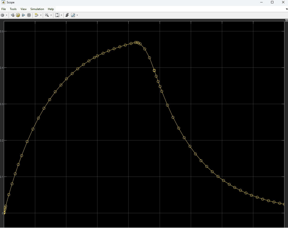
Results
0 to 600 - Heating Mode
Ambient = 5°C
Cabin temperature towards setpoint 22°C
PID output ramps to 0.5°C
600 to 1800 - Cooling Mode
Ambient = 30°C
Cabin temperature drops due to negative control signal
PID output inverts and decays smoothly
Heating Phase : Cabin temp reaches 22°C by 580s
Cooling Phase : Cabin temp drops from 30°C to <10°C by 1300s
Control Effort
Max Heater power : 0.5
Max Cooler power : -0.5
No oscillations
Observations -
PID response is critically damped
Mode switch is stable
First order plant realistic
Fast convergence in both directions
